
English
- English
- беларускі
- Hrvatski
- Тоҷикӣ
- O'zbek
- Español
- Português
- русский
- Français
- 日本語
- Deutsch
- tiếng Việt
- Italiano
- Nederlands
- ภาษาไทย
- Polski
- 한국어
- Svenska
- magyar
- Malay
- বাংলা ভাষার
- Dansk
- Suomi
- हिन्दी
- Pilipino
- Türkçe
- Gaeilge
- العربية
- Indonesia
- Norsk
- تمل
- český
- ελληνικά
- український
- Javanese
- فارسی
- தமிழ்
- नेपाली
- български
- ລາວ
- Latine
- Қазақша
- Euskal
- Azərbaycan
- Slovenský jazyk
- Lietuvos
- Eesti Keel
- Română
- Slovenski
- Srpski језик

Products
Mechanical Linear Drive Racks
Mechanical linear drive racks are essential power transmission components that convert rotary motion from a pinion gear into precise linear movement. They are widely used in CNC machinery, automated assembly lines, packaging equipment, and robotic positioning systems where repeatable straight-line motion is critical. Our catalogue includes a complete range of rack types to suit different load profiles, speed requirements, and environmental conditions. For structural rigidity and high load capacity, Steel Gear Rack Bars are manufactured from normalized carbon or alloy steel with consistent tooth geometry and tight dimensional tolerances. In applications with frequent start-stop cycles or abrasive operating conditions, Hardened Linear Gear Strips provide induction-hardened or case-hardened contact surfaces that significantly reduce wear and extend service intervals. When weight reduction or specific strength characteristics are required, Alloy Transmission Gear Racks offer advanced alloy compositions with improved tensile and yield strength compared to standard carbon steel. For high-precision motion platforms, optical inspection systems, and semiconductor handling equipment, Machined Straight Tooth Rack Bars are ground or shaved after heat treatment to achieve accurate pitch deviation and minimal backlash. All rack series conform to DIN 3962 and ISO 1328 quality grades, with optional certificate of conformity and full dimensional inspection reports. Standard pressure angle is 20°, with straight tooth form for efficient power transmission along the rack axis. Racks can be supplied as individual segments or pre-assembled multi-section lengths for longer travel axes.
Technical Specifications for Mechanical Linear Drive Racks
Mechanical Linear Drive Racks are offered in a modular system that covers the most common industrial drive requirements. The product name refers to the complete series of straight-tooth rack configurations, including standard stock lengths and custom-machined versions. Each rack is manufactured with a full tooth depth that matches standard pinion geometries, ensuring smooth engagement and uniform load distribution along the contact line. The following list summarizes the core configuration options.
- Material grades: C45 carbon steel, 40Cr alloy steel, 42CrMo high-strength steel, 20CrMnTi case-hardening steel, and stainless steel 304/316 for corrosive environments
- Tooth profile: straight tooth form per DIN 867, 20° pressure angle, full depth
- Accuracy classes: DIN 6, DIN 7, DIN 8, DIN 9
- Tooth finishing: milled, induction hardened, ground, or shaved
- Length range: 500 mm, 1000 mm, 1500 mm, 2000 mm, and custom up to 3000 mm
- Face width: 20 mm to 60 mm standard, 10 mm to 120 mm custom
- Surface treatment: black oxide, zinc plating, nickel plating, or uncoated for oil-lubricated systems
- Mounting options: drilled and counterbored holes, threaded holes, or plain ends for butt mounting with alignment keys
The table below provides the primary dimensional and performance parameters for Mechanical Linear Drive Racks. Use these values as a selection guide when matching rack modules to pinion gears and drive motors.
| Parameter | Standard Value | Optional / Custom Range |
|---|---|---|
| Module | 1.0 – 6.0 mm | 0.8 – 10.0 mm |
| Face width | 20 – 60 mm | 10 – 120 mm |
| Total length | 500 – 2000 mm | Up to 3000 mm |
| Hardness | Surface hardened 50 – 55 HRC | Through hardened 40 – 45 HRC |
| Accuracy grade | DIN 7 | DIN 6 ground |
| Backlash | 0.03 – 0.08 mm | < 0.02 mm for ground racks |
| Max feed force | Up to 12 kN per rack | Higher with multi-rack assembly |
| Operating temperature | -20 °C to +120 °C | Special alloy for extreme conditions |
In addition to the dimensional parameters, mounting tolerances and pinion compatibility directly affect the service life and positioning accuracy of Mechanical Linear Drive Racks. The mounting surface should be machined flat within 0.05 mm per 1000 mm of rack length. For ground racks, the cumulative pitch error over 300 mm is held within 0.012 mm to ensure smooth meshing with precision pinions. Induction-hardened racks retain a tough core while providing a hardened tooth flank depth of 0.8 – 1.2 mm. Butt-jointed rack sections are supplied with alignment dowels and machined ends to maintain pitch continuity across the joint. Lubrication can be applied via grease nipples or automatic oil mist systems. For high-speed traverse applications above 2 m/s, ground and shaved tooth finishes are recommended to reduce acoustic noise and dynamic loading. The maximum recommended pinion speed depends on the module and accuracy class, but standard configurations support pinion speeds up to 1800 rpm for module 2 straight tooth racks. Custom pitch errors, non-standard pressure angles, and special end treatments can be quoted upon request.
Related Products




Hot Products
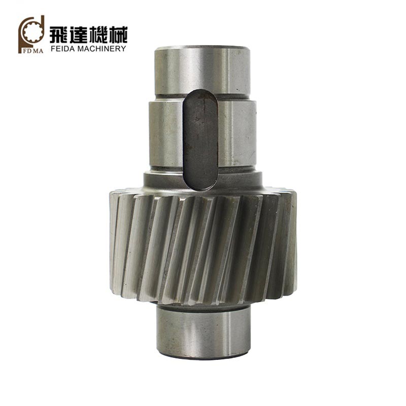
Helical Gear Shafts
Jinjiang Feida Machinery Co., Ltd. has been engaged in transmission parts manufacturing since 1988.The transmission parts include helical gear shafts,gears,spline shafts,etc.OEM & ODM services are acceptable.Welcome to contact us. Hope to build business relationship with you!
Spur Gear Shafts
High quality and good price spur gear shafts are offered by Feida Machinery factory.We have more than 30 years’ experience in the industry ,high quality raw materials, high production standards, and a highly specialized team.Hope to build business relationship with you!
Stepped Shafts
Since its establishment,Feida Machinery has been dedicated to the production and processing of precision shafts(such as stepped shafts and linear shafts), accumulating rich industry experience and professional expertise.Welcome to contact us!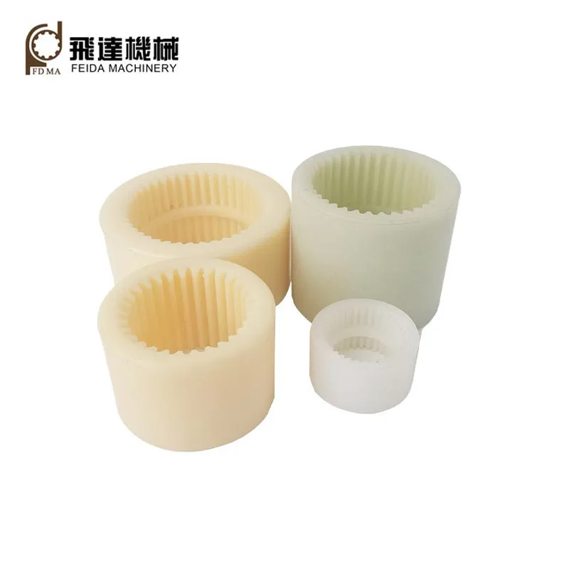
Plastic Internal Gears
As a professional manufacturer, Feida Machinery factory would like to provide you high qulaity plastic internal gears.
Covering a total area of 45,000 sqm, with a workshop of 30,000 sqm, our factory is equipped with state-of-the-art production and inspection facilities to meet diverse customer needs.Welcome new and old customers to continue to cooperate with us to create a better future!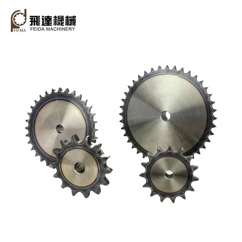
Metal Sprocket Gears
Feida Machinery factory was founed in 1988.It is committed to provide superior metal sprockets gears and perfect services to our customers from then on.Welcome new and old customers to continue to cooperate with us to create a better future!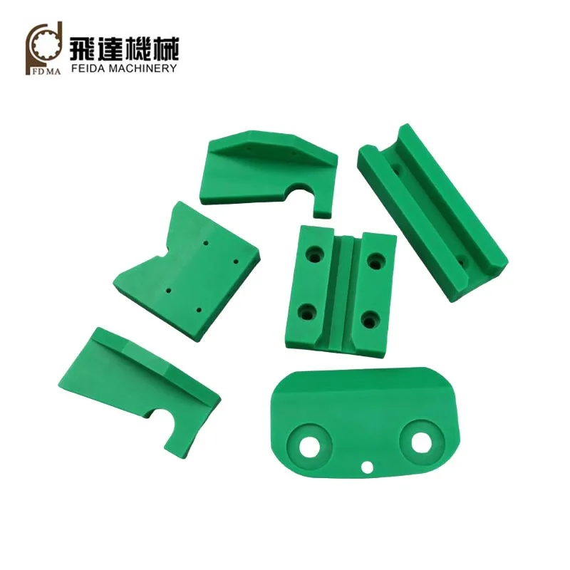
Cnc Plastic Machining
As a china professional manufacturer, exporter,Feida would like to provide you high quality Cnc Plastic Machining parts. OEM and ODM services are acceptable.We welcome to contact us for coopration!
- Related Blog
- Reviews
