
English
- English
- беларускі
- Hrvatski
- Тоҷикӣ
- O'zbek
- Español
- Português
- русский
- Français
- 日本語
- Deutsch
- tiếng Việt
- Italiano
- Nederlands
- ภาษาไทย
- Polski
- 한국어
- Svenska
- magyar
- Malay
- বাংলা ভাষার
- Dansk
- Suomi
- हिन्दी
- Pilipino
- Türkçe
- Gaeilge
- العربية
- Indonesia
- Norsk
- تمل
- český
- ελληνικά
- український
- Javanese
- فارسی
- தமிழ்
- नेपाली
- български
- ລາວ
- Latine
- Қазақша
- Euskal
- Azərbaycan
- Slovenský jazyk
- Lietuvos
- Eesti Keel
- Română
- Slovenski
- Srpski језик

Products
China Metal Helical Pinion Sets Manufacturer, Supplier, Factory
In precision drive engineering, the choice of pinion and wheel directly affects mesh efficiency, thermal stability, and long-term wear performance. Helical tooth geometry offers progressive contact engagement, which lowers impact loading when compared with straight-cut gears and makes the system suitable for reversing or high-cycle operations. The current product range is organized into four categories: Steel Helical Gear Components for standardized gearbox replacements, Alloy Helical Transmission Gears for high-torque drivetrains, Metallic Helical Gear Wheels for continuous-duty conveying and mixing systems, and Industrial Helical Metal Gear Parts for heavy machinery and retrofit projects. The following parameters represent the standard production envelope and are verified by in-house metrology before dispatch. For original equipment manufacturers and maintenance teams, these standardized dimensional envelopes reduce design lead time and allow direct replacement of worn gears without changing housing geometry.
- Material options: 20CrMnTi, 42CrMo, 40CrNiMo, 17-4PH stainless steel; carburizing depth 0.8–1.4 mm for case-hardened grades
- Tooth geometry: involute helical profile, 20° normal pressure angle, 10°–30° helix angle, left-hand or right-hand orientation
- Module range: 0.8–8 mm; pinion teeth: 9–45; wheel teeth: 20–200; single-stage ratio from 1:1 to 6:1
- Accuracy class: DIN 3962 grade 6–8, AGMA 2000-A88 class 8–10, total profile deviation ≤ 10 µm on ground flanks
- Heat treatment: carburizing, induction hardening, nitriding, or carbonitriding; surface hardness 55–62 HRC, core hardness 30–42 HRC
- Mounting configuration: plain bore with keyway per DIN 6885, H7 tolerance, optional shrink disc, taper bushing, or integral shaft
- Additional features: tip relief, longitudinal crowning, shot peening on request, and anti-rust protective coating
| Parameter | Standard Range | Custom Capability |
|---|---|---|
| Pitch Diameter | 15–320 mm | Up to 560 mm |
| Bore Diameter | 8–110 mm | Up to 190 mm |
| Face Width | 12–95 mm | Up to 165 mm |
| Max Transmitted Torque | 1,250 Nm | 3,800 Nm |
| Operating Speed | 1,500 rpm | 4,500 rpm |
| Measured Backlash | 0.05–0.12 mm | 0.02–0.04 mm |
| Noise Level at 3,000 rpm | ≤72 dB(A) | ≤65 dB(A) |
| Surface Roughness on Flank | Ra 0.8–1.6 µm | Ra 0.4–0.8 µm |
Metal Helical Pinion Sets are produced as matched pairs with traceable set numbers to maintain exact center-distance control and uniform contact patterns across the full face width. Manufacturing starts with forged or rolled billet stock, followed by normalizing, rough turning, CNC hobbing, heat treatment, finish boring, and profile grinding or honing. Pinions intended for high-speed use are induction-hardened by single-shot or scanning processes, then ground on the bore, journal diameters, and tooth flanks in a single setup to minimize runout. Case-carburized sets are treated to a controlled case depth of approximately 0.1–0.2 times the module and tempered to relieve grinding stress. Each tooth flank receives tip relief and longitudinal crowning, which reduces edge loading when the housing deflects under load and keeps the contact ellipse close to the center of the face width. The standard surface finish on ground flanks is Ra 0.4–0.8 µm, while the bore is finished to H7 or IT5 depending on the speed requirement. Runout of the pitch circle relative to the bore is held to 0.02 mm or better, and the tooth root fillet can be shot-peened to increase bending fatigue strength by approximately 15–20 percent. Splined bores, keyways, and set-screw flats are machined after final hardening to preserve their positional relationship to the gear teeth. The maximum operating temperature is 150°C for standard alloy grades and 200°C for nitrided versions. Lubrication cross-drilled holes and axial oil grooves can be added for continuous oil supply in high-speed gearboxes. Metal Helical Pinion Sets are suitable for servo drives, rack-and-pinion actuators, agricultural transmissions, packaging lines, and industrial automation axes where low backlash and repeatable positioning are required. Standard delivery includes a dimensional inspection report, material certification, and anti-rust packaging in VCI film. Optional dynamic balancing to ISO 1940 G1, magnetic particle inspection, and ultrasonic testing of the tooth root region are available for critical installations. The gear sets are inspected on Klingelnberg P-series or Zeiss Contura machines, and measurements include involute form, helix angle, tooth thickness, tip diameter, and base tangent length. Each batch is checked for material hardness with a Rockwell tester and for case depth with a Vickers microhardness traverse. All test reports are archived by serial number and can be supplied with the shipment. Standard pinion shafts are stress-relieved after rough machining, and the journals are ground to a circularity of 1.5 µm for speeds above 2,000 rpm. Balancing is performed on two-plane machines, and corrections are applied by drilling or milling the gear body without affecting the tooth load rating. Coating and plating options include black oxide, phosphate, and electroless nickel for corrosive environments. The overlapping contact ratio of the helical mesh, typically 1.8–2.4, distributes the transmitted load over multiple teeth and reduces peak stress at the root. This results in lower noise, smoother torque transfer, and longer service intervals in continuous or reversing applications.
Related Products



Hot Products
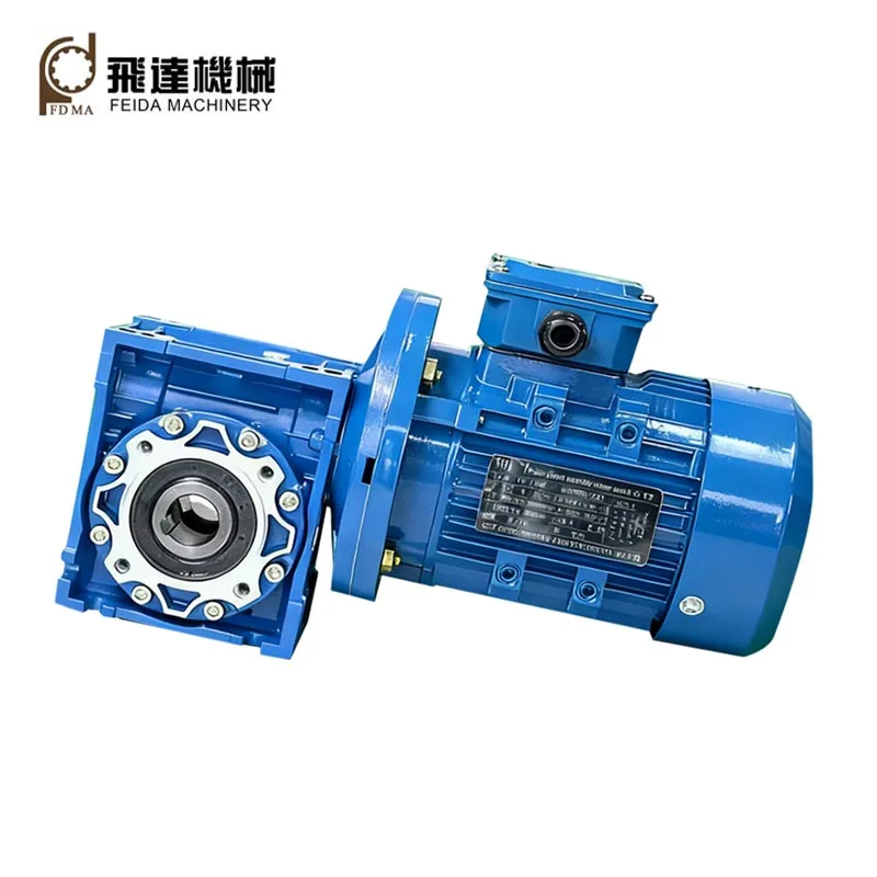
Worm Gear Reducers
Feida Machinery produces high quality worm gear reducers using advanced cnc machining technology and premium raw materials.We look forward to cooperating with you!
Sheet Metal Assembly
Feida Machinery has 15+ years of experience in sheet metal assembly service.
Depending on the high quality and superior service,We have earned the trust of new and old clients at home and abroad. Welcome to contact us for cooperation!
Plastic Gear Racks
With many years' production experience of plastic gear racks, Feida Machiney factory will be trusted by our advantages in competitive price, on-time delivery, good quality, on-hand engineering support and good after-sales services.OEM & ODM are acceptable.Welcome to contact us!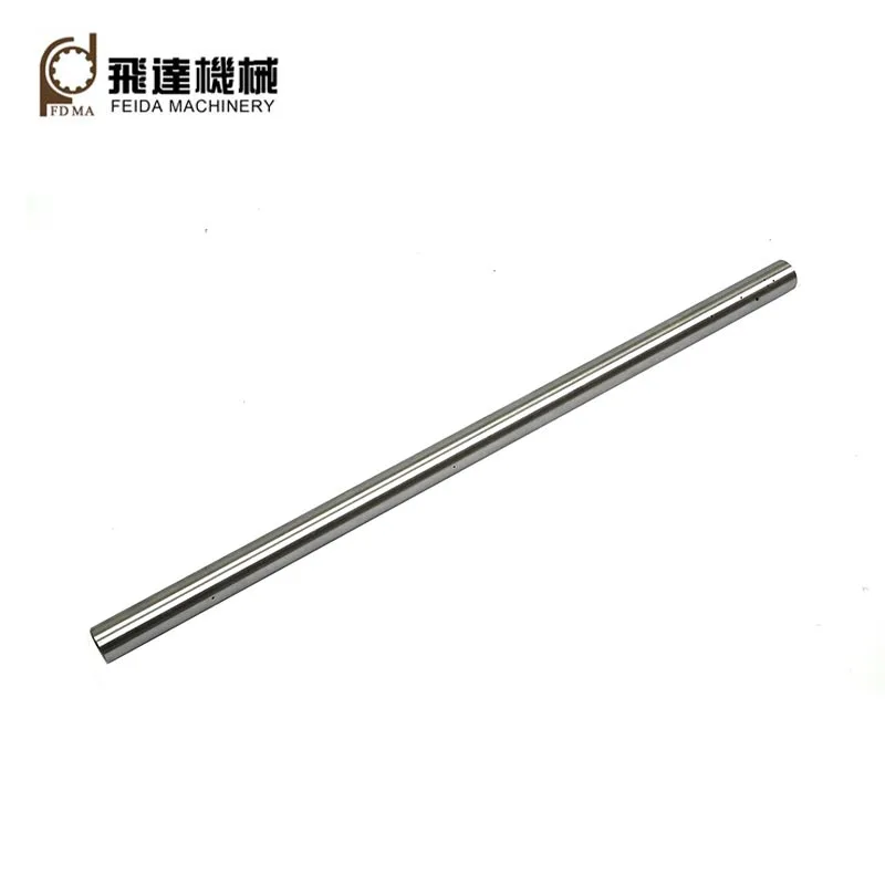
Linear Shaft
With over 30 years of customization experience,Feida Machinery factory can provide premium Linear shafts for our clients.Our products are according to ISO and DIN standard.We look forward to cooperating with you!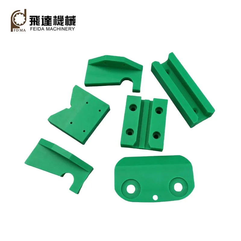
Cnc Plastic Machining
As a china professional manufacturer, exporter,Feida would like to provide you high quality Cnc Plastic Machining parts. OEM and ODM services are acceptable.We welcome to contact us for coopration!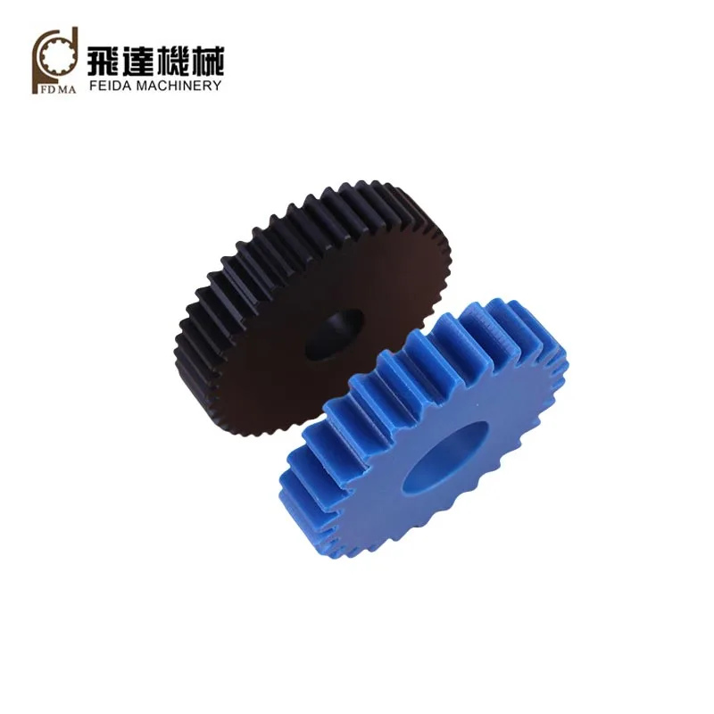
Plastic Spur Gears
The plastic spur gears from Feida Machinery factory offer many advantages,such as an extremely light weight,excellent corrosion resistance,good insulation,low cost,low noise,and good self-lubrication,which satisfy our clients at home and abroad.Hope to build business relationship with you!
- Related Blog
- Reviews
