
English
- English
- беларускі
- Hrvatski
- Тоҷикӣ
- O'zbek
- Español
- Português
- русский
- Français
- 日本語
- Deutsch
- tiếng Việt
- Italiano
- Nederlands
- ภาษาไทย
- Polski
- 한국어
- Svenska
- magyar
- Malay
- বাংলা ভাষার
- Dansk
- Suomi
- हिन्दी
- Pilipino
- Türkçe
- Gaeilge
- العربية
- Indonesia
- Norsk
- تمل
- český
- ελληνικά
- український
- Javanese
- فارسی
- தமிழ்
- नेपाली
- български
- ລາວ
- Latine
- Қазақша
- Euskal
- Azərbaycan
- Slovenský jazyk
- Lietuvos
- Eesti Keel
- Română
- Slovenski
- Srpski језик

Products
Industrial Helical Metal Gear Parts
Industrial helical metal gear parts are at the heart of heavy-duty power transmission systems where smooth meshing, high torque density, and low operating noise are required. Our manufacturing scope includes Steel Helical Gear Components made from carburizing-grade steel for maximum core toughness, Alloy Helical Transmission Gears engineered from nickel-chromium-molybdenum alloys for superior fatigue resistance, Metal Helical Pinion Sets supplied as matched pinion and gear pairs with fully conjugate tooth contact, and Metallic Helical Gear Wheels with ground or skived profiles for AGMA Class 10 and higher accuracy. Helical tooth geometry provides gradual engagement, which reduces impact loading and noise compared with spur gears, making these parts suitable for pumps, compressors, conveyors, and off-highway final drives. The core design envelope and production capabilities are listed below.
- Material options: 20CrMnTi, 42CrMo, 17CrNiMo6, 20MnCr5, 8620, 4340, EN36C, 4140, 4150, and 316 stainless on request.
- Module range: 1.0–16 mm normal module; 0.5 mm available for instrument drives.
- Pressure angle: 20° standard; 14.5° and 25° optional for special load and backlash needs.
- Helix angle: 10°–45°, commonly 15°, 20°, 25°, and 30° for balanced axial thrust.
- Tooth accuracy: DIN 3962 grade 5–8, AGMA 2015 class 10–13, JIS B 1702 grade 2–4.
- Hardness after heat treatment: HRC 58–62 case depth 0.6–1.8 mm; through-hardened options HRC 32–45.
- Surface finish: Ra 0.4–0.8 μm ground; Ra 1.6–3.2 μm shaved or hobbed.
- Max dimensions: outside diameter up to 1,500 mm, face width up to 600 mm, weight up to 3,000 kg per piece.
- Bore and hub configuration: plain bore, keyway, spline, shrink disc, or integral shaft.
- Surface treatments: carburizing, induction hardening, nitriding, carbonitriding, black oxide, phosphating, zinc plating.
- Tooth modifications: tip relief, root relief, lead crowning, bias modification, topological correction.
- Noise control: profile crowning 5–20 μm, helix crowning 5–25 μm, lead slope correction 0–10 μm.
- Balancing: dynamic balancing to G2.5 or G1.0 for high-speed gear shafts.
- Custom features: oil holes, keyways, splines, set screw holes, tapped puller holes, shoulder pins.
- Prototyping: 3D CAD models, FEA tooth contact analysis, reverse engineering from worn samples.
| Parameter | Standard Capability | Custom / High-Precision Option |
|---|---|---|
| Material | 20CrMnTi, 42CrMo, 8620 | 17CrNiMo6, 4340, 9310, stainless steel |
| Module (normal) | 1.0–10 mm | 0.5–16 mm |
| Pressure angle | 20° | 14.5° / 25° |
| Helix angle | 15°–30° | 10°–45° |
| Accuracy grade | DIN 7 / AGMA 11 | DIN 5 / AGMA 13 |
| Tooth surface hardness | HRC 58–60 carburized | HRC 60–62 with controlled case depth |
| Heat treatment | Carburizing, induction hardening | Nitriding, carbonitriding, through hardening |
| Tooth modification | Tip relief, lead crowning | Topological modification from FEM load analysis |
| Gear type | External helical, internal helical | Double helical, helical rack, pinion shaft |
| Maximum outside diameter | 800 mm | 1,500 mm |
| Maximum face width | 300 mm | 600 mm |
| Surface roughness (flank) | Ra 0.8 μm | Ra 0.4 μm polished |
| Max pitch line velocity | 20 m/s | 40 m/s with ground and balanced set |
| Quality system | ISO 9001 | IATF 16949, ISO 14001 |
Industrial Helical Metal Gear Parts are produced under a fully traceable process chain that begins with certified round bar or forged blanks and ends with CMM inspection and rust-preventive export packaging. Typical workflow includes saw cutting, normalizing, turning, hobbing or gear shaping, deburring, carburizing or induction hardening, bore grinding, and tooth grinding on CNC gear grinders with on-machine gear inspection. For high-volume automotive and agricultural applications, gear skiving and power honing deliver DIN 7 accuracy at competitive cycle times. For wind turbine, mining, and steel mill gearboxes, deep case carburizing with shot peening increases root bending fatigue life by 25–35% compared with untreated surfaces. Additional processes such as nitriding, carbonitriding, black oxide coating, and phosphating are available for special corrosion or wear requirements. For replacement and aftermarket needs, we reverse engineer worn or failed gear sets using 3D scanning and gear calculation software, then supply upgraded materials and tooth modifications to extend service life. Standard bore tolerances are H7, with keyway per DIN 6885 or ANSI B17.1, and face runout controlled within 0.02 mm per 100 mm diameter. When high-speed operation is required, AGMA Class 12 or better ground gears with dynamic balancing to G2.5 and oil jet lubrication ports in the web are recommended. Each production lot is verified with a Klingelnberg gear measuring center, double flank rolling tester, and tooth root magnetic particle inspection. Dimensional reports, material certificates, and PPAP Level 3 documentation are provided as standard for serial orders. All parts are shipped with VCI paper, silica gel, and export-grade plywood crates to prevent corrosion during ocean freight. Typical lead time is 18–25 days for prototype quantities and 30–40 days for mass production, depending on blank availability, heat treatment batch size, and tooth grinding capacity.
Related Products


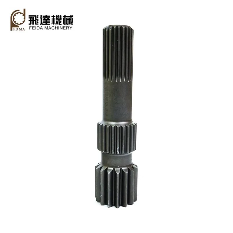
Hot Products
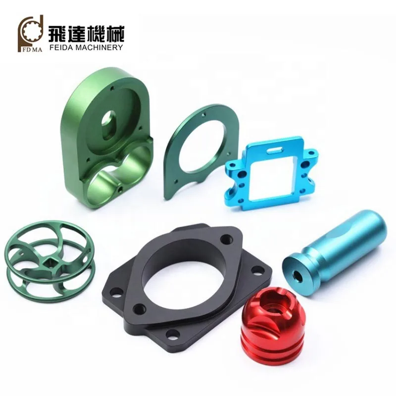
Aluminium Cnc Machining
With more than 30 years of technical accumulation, Feida Machinery always focus on the research and development, production and sales of Aluminium Cnc Machining spare parts, continuously introduce advanced equipment, constantly carry out self-technology revolution, keep up with the development of advanced technology, and provide excellent solutions for clients.Welcome new and old customers to continue to cooperate with us to create a better future!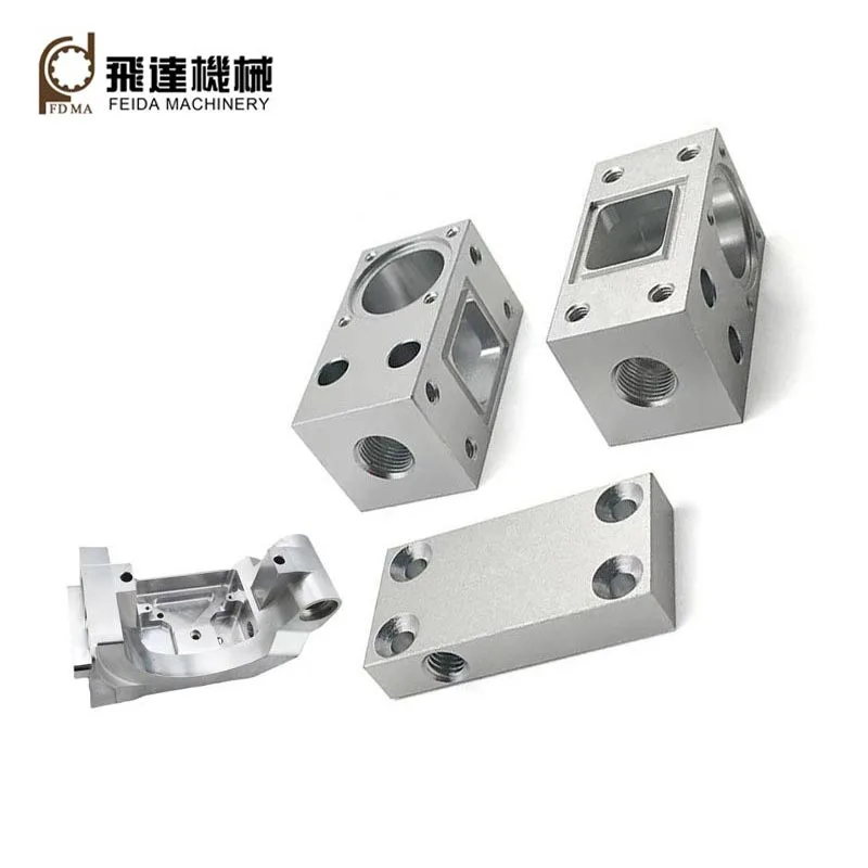
CNC Wire-electrode Cutting
High quality CNC wire-electrode cutting parts are offered by a China manufacturer ,Feida Machinery. Our factory has been producing and processing parts for more than 30 years and has received praise from clients at home and abroad. Welcome to contact us for customization!
Metal Spur Gears
Metal spur gears are well known for their high transmission efficiency ,whose precision grade is up to ISO/DIN 5-10 level.Feida Machinery factory has a highly skilled team and advanced cnc machines to provide the one-stop service from design to delivery.OEM and ODM services are available.Welcome to contact us!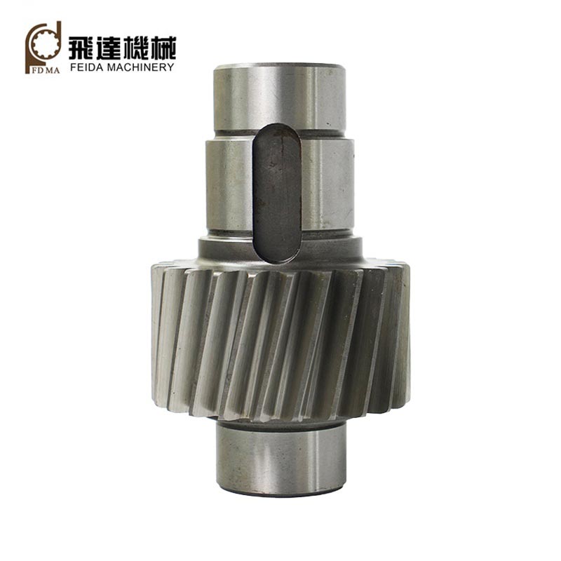
Helical Gear Shafts
Jinjiang Feida Machinery Co., Ltd. has been engaged in transmission parts manufacturing since 1988.The transmission parts include helical gear shafts,gears,spline shafts,etc.OEM & ODM services are acceptable.Welcome to contact us. Hope to build business relationship with you!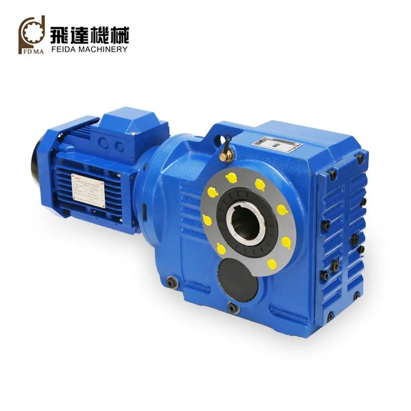
Helical gear reducers
Since it was founded in 1988,Feida Machinery has been specialized in manufacturing a wide range of high-quality helical gear reducers,OEM &ODM service is acceptable,Welcome to contact us!
Linear Shafts
With over 30 years of customization experience,Feida Machinery factory can provide premium Linear shafts for our clients.Our products are according to ISO and DIN standard.We look forward to cooperating with you!
- Related Blog
- Reviews
